
How to wire an LED to the GPIO (and make it blink!)
In this tutorial we will be taking a look how to wire an LED to the GPIO.
Requirements:
- Raspberry Pi with Raspberry Pi OS installed (Any model will work)
- Jumper wires
- 1 LED
- 220 Ohm resistor
Wiring the GPIO

You will need to wires plugged into the GPIO. One from 3.3V which is the first pin on the left with the USB ports facing down. The second pin is GND which is the 3rd pin on the right.
Wiring the breadboard
If you don’t know how a breadboard works, I suggest you check out this short tutorial before continuing!
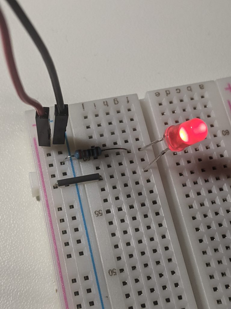
Connect the 3.3V wire (red) to the positive(+) rail on the breadboard and connect the GND wire (black) to the negative (-) rail:
Connect another wire from the + rail to the long pin on the LED. Next, place a resistor running from the negative rail.
That’s it! If you have followed this tutorial successfully you should have an LED that is powered on.
Making the LED flash
Now, let’s have a look at how we can make the LED flash. There are numerous ways of accomplishing this but the easiest way is to use Python.
To make the LED flash you will need to periodically send power. Above, we connected the power source to 3.3V. There are other pins on the GPIO that allow you to turn that voltage off and on. With that said, lets change the power wire (red in my case) to a different pin. I have moved the 3.3V wire to GPIO pin 26. This pin is located second from the bottom on the left side of the Raspberry Pi.

Writing Python code to make the LED flash
After everything has been wired up correctly, let’s start writing the Python code. The Python code will be able to set the GPIO pin high(3.3V) or low (0V). This will give the LED a flashing effect.
I will be using ssh and vi to write the Python code for this tutorial but feel free to use your favorite editor. Create a new python file and name it LED-flash.py.
vi LED-flash.pyImport the GPIO library(RPi.GPIO) to control the GPIO and also the time library(time):
import RPi.GPIO as GPIO
import time
Next, let’s disable warning for the GPIO. Warning’s can happen when we don’t cleanup the GPIO probably but they are safe to ignore.
GPIO.setwarnings(False)Now you will need to set the mode of the GPIO to BCM. This wll allow us to refer to the pins by Broadcom SOC channel number. An explanation of this can be found here.
GPIO.setmode(GPIO.BCM)The last thing to setup is the GPIO pin itself. You will want to define 26 as an output with an initial value of GPIO.LOW. This means that when the Python program is run, the LED will be in an off state.
GPIO.setup(26, GPIO.OUT, initial=GPIO.LOW)Finally, since we want our LED to flash, you will need to setup an infinite while loop and alternate the pin between GPIO.HIGH and GPIO.LOW. We will also add a sleep for 1 second so that the LED turns on for one second and turns off for one second.
while True:
      GPIO.output(26, GPIO.HIGH)
      time.sleep(1)
      GPIO.output(26, GPIO.LOW)
      time.sleep(1)
That’s it! Execute the program using Python and you should now have a flashing LED! To stop the execution of the program use CTRL + C.